
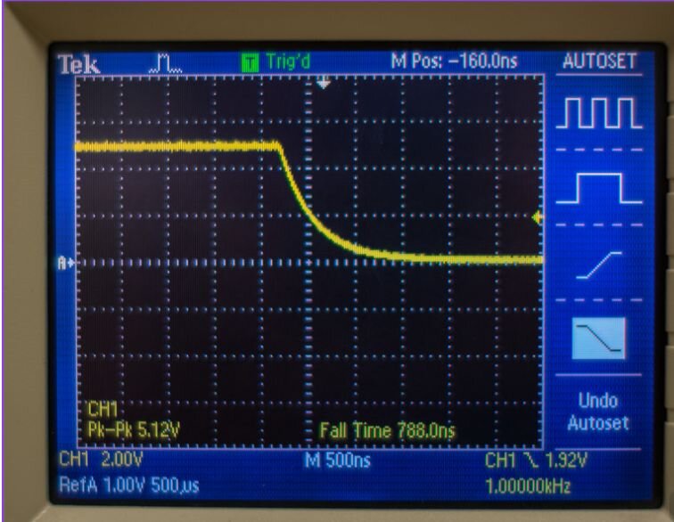
When I first learned to use an oscilloscope, the focus was always on the familiar controls: time base, voltage scale, triggering, getting a clean and stable trace. What was rarely discussed was something far more fundamental to an accurate measurement: the difference between the x1 and x10 setting on the probe.
The signal that looked wrong
A while back, while working on a project, I ran into a strange problem. The signal I was measuring looked nothing like what I expected. Edges were rounded, the waveform seemed sluggish, and it looked as if the circuit had suddenly gained a large amount of capacitance.
The first thing I blamed was the circuit. Only after digging deeper did I realise the issue had nothing to do with the design. The real culprit was the probe itself.
What the switch actually changes
A probe is not a perfect window into your circuit. It is a load connected to it, and the x1/x10 switch changes how big that load is.
- x1: the probe is essentially a shielded cable straight into the scope's input. Your circuit sees the scope's input resistance (typically 1 MΩ) plus the capacitance of the cable and the input, often somewhere around 50 to well over 100 pF in total. Bandwidth in x1 mode is also usually limited to just a few MHz.
- x10: a compensated 9 MΩ divider in the probe tip forms a 10:1 divider with the scope input. The circuit now sees about 10 MΩ and only around 10–15 pF, and you get the probe's full rated bandwidth.
On a high-impedance node or a fast edge, that extra capacitance in x1 mode forms an RC low-pass filter with the source impedance. The rounded, slow edges I was seeing were real, but they were being created by my measurement, not by my design.
When to use which
- Use x10 by default for digital signals, clocks, edges, anything above a few hundred kHz, and any high-impedance node.
- Use x1 only for small, slow signals where you need the extra sensitivity, such as low-level ripple on a low-impedance supply, and keep in mind the bandwidth limit.
- Tell the scope which one you're using. If the channel is set to x1 while the probe is on x10, every reading is ten times too small.
- Compensate x10 probes. Connect them to the scope's calibration square wave and adjust the trimmer until the corners are flat, neither overshooting nor rounded.
- Mind the ground lead. For fast edges, a long ground clip adds its own ringing. A short ground spring on the probe tip often makes a dramatic difference.
The lesson
That moment of realising the difference between x1 and x10 solved my problem, and it reminded me how important it is to understand not just the oscilloscope's settings but how the probe interacts with the circuit. Before you start redesigning hardware because a waveform looks wrong, check what your measurement is doing to it.
Have you ever chased a problem that turned out to be your measurement setup? We'd love to hear about it.